
⚡ Quick Specs: Inconel 625 Seamless Pipe
🛠 Full Production Flow: Inconel 625 Seamless Pipe
1. Introduction: Why Inconel 625 Seamless Pipe?
Inconel 625 (UNS N06625 / W.Nr. 2.4856) is one of the most widely specified nickel-chromium-molybdenum alloys in the world. With its unique combination of solid-solution strength, ductility, weldability, and resistance to pitting, crevice corrosion, chloride stress-corrosion cracking, and oxidation at temperatures up to 980 °C, Inconel 625 seamless pipe is the material of choice for critical service in chemical processing, aerospace, marine, oil & gas, and power generation.
But the performance of Inconel 625 seamless pipe does not come from chemistry alone — it comes from how the pipe is made. The manufacturing process — from the first melt to the final non-destructive test — determines the grain structure, inclusion cleanliness, dimensional precision, and pressure integrity of the finished product. A sub-par billet or a poorly controlled annealing cycle can turn a promising heat of 625 into pipe that fails prematurely in service.
At Shanghai Hangbo Alloy Group, we produce Inconel 625 seamless pipe to ASTM B444 / ASME SB-444 using a fully integrated VIM+ESR melting, hot extrusion, cold pilgering, and solution-annealing route — with 100% NDT inspection on every single pipe. This article walks through every step in that process, explaining not just what we do, but why each step matters.
2. Stage 1: Raw Material Selection & Precision Alloying
2.1 Raw Material Procurement
Quality starts before the furnace is lit. Every incoming raw material — electrolytic nickel (Ni ≥99.96%), chromium metal (Cr ≥99.5%), molybdenum powder or briquettes, niobium (Nb ≥99.9%), and iron — is sourced from qualified, audited suppliers with full Certificates of Analysis (COA). At Hangbo Alloy Group, each incoming lot is independently re-verified by Optical Emission Spectroscopy (OES) and Carbon/Sulfur analyzer before it enters the furnace bay. Any lot that deviates from specification by more than 0.02% is rejected.
Key control point: Tramp elements — lead, bismuth, selenium, tellurium, and antimony — must all be below 5 ppm each. These five elements are potent grain-boundary embrittlers in nickel alloys, and there is no acceptable "trace level" for them in aerospace-grade Inconel 625.
2.2 VIM — Vacuum Induction Melting
The first melt is performed in a vacuum induction furnace operating at 10⁻¹ to 10⁻³ Pa absolute pressure. The vacuum environment serves three purposes:
- Degassing: Hydrogen (H₂), oxygen (O₂), and nitrogen (N₂) dissolved in the liquid metal are drawn out. Our target post-VIM oxygen level is ≤20 ppm — well under the ASTM B444 requirement.
- Tramp element volatilization: Low-boiling-point impurities (Pb, Bi, Zn, Sn) are evaporated under vacuum.
- Precision chemistry control: With no atmospheric contamination, chromium recovery is near 100%, and niobium losses are minimized. Our VIM chemistry control window for Cr, Mo, and Nb is ±0.15% — far tighter than the ASTM-allowed range.
The VIM ingot is cast into water-cooled copper molds, typically producing a 1–3 ton electrode measuring 300–500 mm in diameter. At this stage, the ingot still has a coarse columnar cast structure typical of all as-cast nickel alloys — it is chemically correct, but structurally not yet ready for pipe production.
2.3 ESR — Electroslag Remelting
The VIM electrode becomes the consumable electrode in the ESR furnace. In ESR, the electrode tip is immersed in a molten slag pool (typically a CaF₂-CaO-Al₂O₃ system), and a high-amperage AC current passes through the slag, remelting the electrode drop by drop. Each molten droplet passes through the reactive slag, which:
- Reduces sulfur from the typical VIM level of 50–100 ppm down to ≤10 ppm — critical for hot workability of nickel alloys, since sulfur forms low-melting Ni₃S₂ eutectic films at grain boundaries.
- Floats out non-metallic inclusions (oxides, nitrides, silicates) by slag-metal reaction. ESR cleanliness ratings for Inconel 625 are typically ASTM E45 Class A (worst-field ≤0.5).
- Produces directional solidification, eliminating centerline porosity and minimizing macrosegregation. The ESR ingot has a fine, equiaxed structure from bottom to top.
For the most demanding applications (aerospace rotating parts, NORSOK-qualified subsea pipe), a triple-melt route (VIM + ESR + VAR) adds a final vacuum arc remelt to further refine the structure. However, for ASTM B444 seamless pipe in standard industrial service, the VIM+ESR double-melt route delivers the cleanliness and homogeneity required — and this is the standard route at Hangbo Alloy Group.
3. Stage 2: Forging — Breaking the Cast Structure
The ESR ingot must be converted from a cast structure into a wrought structure suitable for pipe production. This is done by open-die forging (cogging) on a hydraulic press or forge hammer.
3.1 Heating and Soaking
The ESR ingot is charged into a gas-fired or electric furnace and heated to 1120 °C with a controlled ramp rate of 60–100 °C/hour to avoid thermal shock cracking. It is soaked at temperature for 30–45 minutes per 100 mm of ingot diameter to ensure through-heating. The furnace atmosphere is controlled (slightly oxidizing) to minimize scaling.
3.2 Cogging Process
Forging begins at ≥1030 °C and must stop before the temperature drops below 930 °C. Below 930 °C, Inconel 625 exhibits significantly increased flow stress, and continued forging risks surface cracking and insufficient recrystallization. The ingot is repeatedly reduced by 20–30% per heat and reheated between forging passes as needed.
The goal of cogging is threefold: (1) break down the columnar dendritic cast structure into a fine, equiaxed, recrystallized grain structure (target ASTM grain size 4–7 after solution annealing); (2) close any residual centerline porosity from casting; and (3) homogenize any remaining microsegregation through thermal diffusion during the forging and reheating cycles.
After the final forging pass, the billet is air-cooled or, for larger sections, transferred to a controlled cooling pit to prevent cracking. The billet is then rough-machined to remove scale and surface defects, center-drilled if required for the piercing operation, and ultrasonically inspected (ASTM A388) to ensure internal soundness before it enters the pipe mill.
4. Stage 3: Hot Piercing & Extrusion — Creating the Hollow Shell
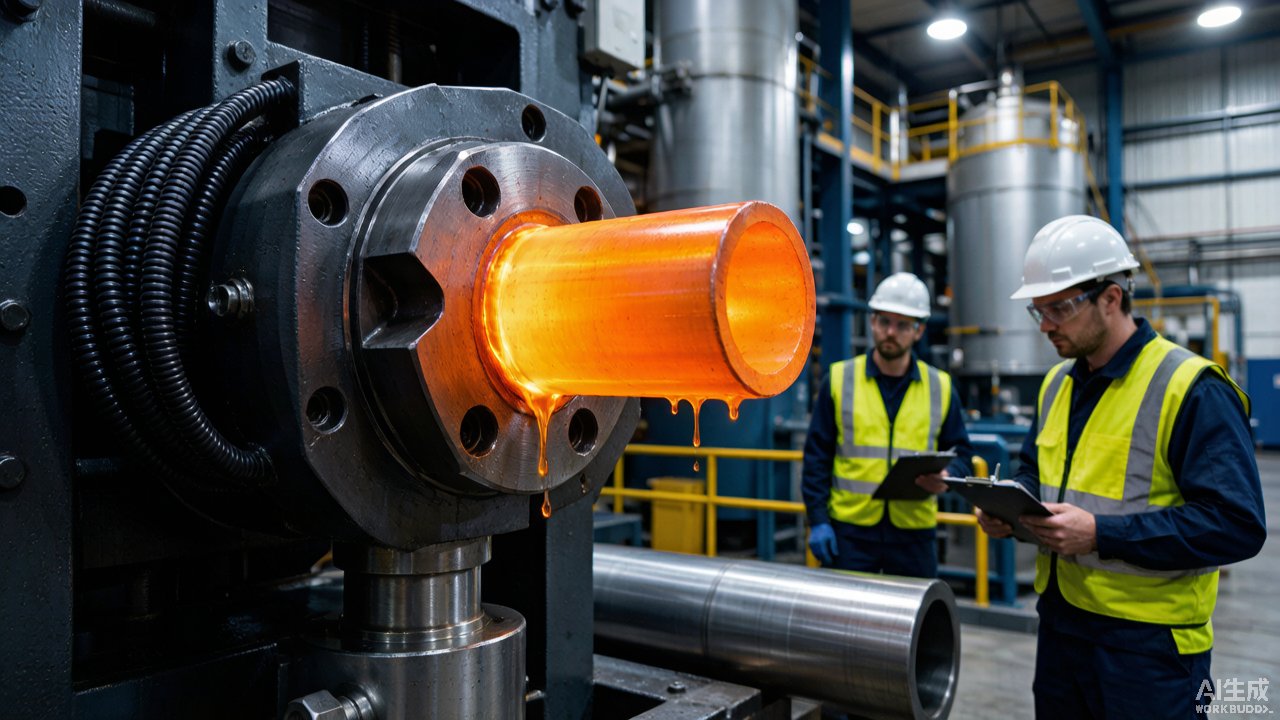
Hot extrusion is the defining step that transforms a solid, forged billet into a hollow pipe shell with no weld seam. At Hangbo Alloy Group, this operation is performed on a horizontal extrusion press.
4.1 Billet Preparation
The machined, UT-inspected billet is reheated to 1150–1200 °C (2100–2190 °F) in a rotary-hearth furnace with ±15 °C uniformity. The high temperature is necessary because Inconel 625 has excellent hot strength — even at 1150 °C, the flow stress is approximately 80–100 MPa, requiring significant extrusion force. The billet surface is coated with glass powder lubricant (borosilicate-based), which melts at extrusion temperature to form a continuous film between the billet, the die, and the container wall. This glass film serves as both a lubricant and a thermal barrier, protecting the tooling and preventing excessive billet cooling.
4.2 Piercing
In the extrusion press, a piercing mandrel first penetrates the center of the heated billet to create the initial bore. The piercing force must overcome the material flow resistance, and piercing speed is carefully controlled to avoid bore eccentricity — a critical quality parameter, since bore eccentricity at this stage propagates through all subsequent cold-working steps.
4.3 Extrusion
After piercing, the main extrusion ram pushes the billet through the annular gap between the die (which controls the OD) and the mandrel (which controls the ID and wall thickness). The extrusion ratio — the ratio of billet cross-sectional area to pipe cross-sectional area — typically ranges from 4:1 to 10:1 for Inconel 625. Higher extrusion ratios produce finer grain structure but require larger presses and more robust tooling.
Key process parameters monitored during extrusion:
- Extrusion speed: typically 50–150 mm/s for Inconel 625. Too fast → surface tearing; too slow → excessive die chilling and work hardening.
- Extrusion temperature decay: the billet must exit the die above ~950 °C to ensure complete dynamic recrystallization. Runout tables may be fitted with water sprays for controlled cooling.
- Die condition: dies are inspected after every extrusion run. Die wear beyond 0.2 mm on the bearing surface is cause for replacement.
The extruded hollow shell, or "mother tube," emerges with a hot-worked, dynamically recrystallized grain structure. At this point it has a rough surface finish and tolerances of approximately ±1.5 mm on OD and ±15% on wall — far from the precision required for finished pipe. It now enters the cold-working stage.
5. Stage 4: Cold Pilgering — Precision Reduction
Cold pilgering (also known as cold rolling) is the primary method for reducing both OD and wall thickness of Inconel 625 seamless pipe while simultaneously improving dimensional precision, surface finish, and mechanical properties through cold work.
5.1 How Cold Pilgering Works
A cold pilger mill consists of a tapered mandrel inside the tube and a pair of grooved rolls on the outside. The rolls reciprocate back and forth over a short stroke (typically 300–600 mm), and between each stroke the tube is rotated and advanced forward by a small feed increment (1–5 mm). The tapered profile of the mandrel and the variable groove depth of the rolls together produce a progressive reduction in both diameter and wall thickness as the tube advances through the mill.
5.2 Cold Pilgering Parameters for Inconel 625
Each cold pilger pass achieves 30–50% reduction in cross-sectional area. The exact parameters depend on the starting and target dimensions:
- Feed rate: 2–4 mm/stroke — lower than for stainless steel due to Inconel 625's higher work-hardening rate.
- Stroke rate: 80–120 strokes/minute.
- Lubrication: chlorinated paraffin oil or synthetic ester-based pilger oil, flooded at the roll gap to dissipate heat and reduce friction.
- Q-value (strain path): carefully calculated to balance OD reduction against wall reduction, maintaining a neutral strain path that avoids wrinkling on the ID.
After one to three pilger passes (each followed by intermediate solution annealing at 1095 °C), the pipe achieves OD tolerances of ±0.1 mm and wall thickness tolerances of ±10% of nominal, with surface finish Ra ≤1.6 µm.
5.3 Why Cold Pilgering, Not Just Cold Drawing?
Cold pilgering provides two advantages over cold drawing for Inconel 625:
- Higher reduction per pass: Pilgering can achieve 50% area reduction in one pass versus ~20% for drawing — reducing the number of intermediate anneals and minimizing energy input.
- Compressive stress state: The rolling action of pilgering places the metal under predominantly compressive stress, which is better tolerated by nickel alloys than the tensile stress in drawing. This reduces the risk of surface micro-cracks in Inconel 625, especially after heavy cold work.
6. Stage 5: Cold Drawing — Precision for Small-Bore Tubing
For smaller-diameter Inconel 625 seamless pipe and instrumentation tubing (typically OD <25 mm), cold drawing supplements or replaces cold pilgering. In the drawing process, the pilgered tube is pulled through a tungsten carbide die (OD control) over a fixed or floating mandrel (ID control).
6.1 Drawing Parameters
- Area reduction per pass: 15–25% for Inconel 625.
- Drawing speed: 10–30 m/min.
- Lubrication: chlorinated drawing soap or molybdenum disulfide paste applied to both the OD and the mandrel surface.
- Die material: tungsten carbide (WC-Co) with diamond-polished bearing surface, Ra ≤0.1 µm.
- Die angle: 12–14° half-angle, optimized for nickel alloys.
After each drawing pass, the tube is intermediate-annealed at 1095 °C to reset the work-hardened structure before the next pass. Multiple drawing passes bring the tube to its final diameter with dimensional tolerances as tight as ±0.05 mm on OD for instrumentation-grade tubing.
7. Stage 6: Solution Annealing — The Critical Heat Treatment
Solution annealing is the single most important heat treatment for Inconel 625 seamless pipe. A poorly executed anneal can leave the pipe with partially dissolved carbides, incipient intergranular attack susceptibility, or inadequate ductility — and no subsequent operation can fix it.
7.1 The Metallurgical Purpose
At the solution annealing temperature of 1095 °C minimum, all niobium-rich MC carbides and chromium-rich M₂₃C₆ carbides that may have formed during hot working or prior thermal exposure are dissolved back into the austenitic matrix. The subsequent water quench freezes this homogeneous, single-phase structure — maximizing corrosion resistance and ductility.
7.2 Hangbo Alloy Group Annealing Parameters
- Furnace: Continuous roller-hearth furnace with multi-zone temperature control, ±10 °C uniformity across the charge.
- Temperature: 1095–1150 °C, selected based on wall thickness and prior cold work.
- Soak time: 15–60 minutes, proportional to wall thickness (approximately 10 minutes per 10 mm wall).
- Atmosphere: Slightly reducing or inert (N₂-H₂ or dissociated ammonia) to minimize surface oxidation.
- Quench: Rapid water quench within 60 seconds of exiting the hot zone. The quench tank is agitated and temperature-controlled (≤40 °C). Any delay in quenching risks sensitization — chromium carbide precipitation at grain boundaries — particularly in higher-carbon heats near the 0.10% limit.
7.3 Quality Verification Post-Anneal
Every heat treatment lot is verified by:
- Hardness testing: Must be ≤220 HB (≤100 HRB) per ASTM B444.
- Grain size: ASTM E112, target ASTM 4–7. Grain size finer than ASTM 8 may indicate incomplete recrystallization; coarser than ASTM 3 suggests overheating.
- Tensile test: One tensile specimen per lot per ASTM E8 — yield strength, tensile strength, and elongation must all meet ASTM B444 minimums.
- Intergranular corrosion test (if specified): ASTM G28 Method A (boiling ferric sulfate – sulfuric acid), maximum corrosion rate typically 0.5 mm/year for properly annealed material.
8. Stage 7: Straightening, Pickling & Surface Conditioning
8.1 Straightening
After quenching, the pipe is straightened on a multi-roll straightening machine (typically 6-roll or 10-roll). For Inconel 625, the rolls are set with a slight offset that progressively corrects bow without introducing residual stress. The target straightness is 1 mm per 1 meter of length, per ASTM B829. For critical applications (e.g., rotating shafts or instrumentation tubing), a tighter spec of 0.5 mm/m can be achieved with additional straightening passes.
8.2 Pickling and Passivation
During extrusion, annealing, and even cold pilgering, a thin oxide scale (primarily Cr₂O₃ and NiO) forms on the pipe surface. This scale is chemically removed by pickling in a mixed acid solution:
- Step 1 — Pre-pickling: Alkaline degreasing or solvent cleaning to remove oil and lubricant residues.
- Step 2 — Acid pickling: Immersion in a solution of 15–20% HNO₃ + 4–6% HF at 50–60 °C for 10–30 minutes, depending on scale thickness. The HF attacks the silica-rich scale, while the nitric acid maintains a passive surface on the base metal to prevent general corrosion.
- Step 3 — Rinse: High-pressure fresh water rinse to remove all acid residues.
- Step 4 — Passivation (optional): For applications requiring maximum corrosion resistance, the pickled pipe is immersed in 20–30% HNO₃ at ambient temperature for 30–60 minutes to build a uniform passive Cr₂O₃ film.
After pickling, the pipe surface is uniformly silvery-white, with no residual scale, no pitting, and no acid staining. The surface finish is visually inspected against acceptance standards.
9. Stage 8: Non-Destructive Testing — The Zero-Defect Gate
NDT is where every Inconel 625 seamless pipe either passes or fails, with no middle ground. At Hangbo Alloy Group, we operate a 100% NDT policy — every single pipe, regardless of order size, receives the full complement of non-destructive tests. No sampling-based shortcuts.
9.1 Ultrasonic Testing (UT) — ASTM E213 / ASTM A388
Ultrasonic testing detects internal defects — cracks, laps, inclusions, laminations — in both the longitudinal and transverse directions.
- Method: Immersion or contact UT with shear-wave probes at 45° and 60° incidence for longitudinal defects; 0° compression-wave probe for wall thickness and lamination checks.
- Frequency: 4–5 MHz for standard wall, 10 MHz for thin-wall (<2 mm).
- Reference standard: A calibration pipe of the same nominal size, material, and surface condition, containing machined notches at 5% of nominal wall thickness depth.
- Acceptance criteria: Any indication exceeding the reference notch amplitude is cause for rejection. No provision for "rounding up" marginal indications.
- Coverage: 100% of pipe body, plus the end zones (typically 50 mm from each pipe end) scanned separately with a hand-held probe.
9.2 Eddy Current Testing (ET) — ASTM E426 / ASTM E571
Eddy current testing provides a complementary surface and near-surface inspection. A differential encircling coil passes the full length of the pipe, inducing eddy currents and detecting any discontinuity — pit, crack, seam, or inclusion — that disrupts the current path.
- Frequency: 10–100 kHz, optimized for the specific OD and wall.
- Reference standard: Through-drilled hole at 0.8 mm diameter (or 1/32") for standard-grade pipe; 0.5 mm for high-sensitivity requirement.
- Acceptance: Any signal exceeding the reference amplitude triggers a manual visual reinspection and, if the indication is confirmed, rejection.
9.3 Hydrostatic Pressure Test
Every pipe is hydrostatically tested to verify pressure integrity. Per ASTM B829, the test pressure is calculated as:
P = 2 × S × t / D
Where S = allowable fiber stress (typically 60% of specified minimum yield strength),
t = wall thickness, and D = outside diameter.
The pipe is pressurized, held for a minimum of 5 seconds (longer for large-bore), and visually inspected for any leakage, weeping, or permanent deformation. Zero leakage is the only acceptable result.
9.4 Positive Material Identification (PMI)
Every heat is verified by portable X-ray fluorescence (XRF) or optical emission spectroscopy (OES) to confirm that the alloy grade is correct. PMI checks for Ni, Cr, Mo, Nb, and Fe — the five key elements that distinguish Inconel 625 from other nickel alloys. Any pipe that returns an ambiguous reading is quarantined for full laboratory OES re-analysis.
10. Stage 9: Destructive Mechanical Testing
While NDT covers every pipe, destructive testing is performed on a statistical basis per heat treatment lot to verify that the bulk mechanical properties and workmanship meet specification.
10.1 Tensile Testing — ASTM E8
One longitudinal tensile specimen per heat treatment lot (≤100 pipes of the same size and heat number). The specimen is machined from a full-section strip or from the pipe wall (for small-bore). Minimum requirements for solution-annealed Inconel 625:
| Property | ASTM B444 Minimum | Hangbo Typical |
|---|---|---|
| Tensile Strength, Rm | ≥ 760 MPa (110 ksi) | 830–900 MPa |
| Yield Strength (0.2%), Rp0.2 | ≥ 345 MPa (50 ksi) | 380–480 MPa |
| Elongation in 50 mm, A% | ≥ 30% | 40–50% |
| Hardness, HB | ≤ 220 HB | 150–190 HB |
10.2 Flattening Test — ASTM A370
A ring cut from the pipe end is flattened between parallel plates to a specified distance without cracking. This test verifies ductility and freedom from defects in the weld-affected zone of the pipe body — for seamless pipe, it primarily validates the absence of lamination defects and adequate hot-working recrystallization.
10.3 Flaring Test (for tube sizes)
A section of tube is expanded over a tapered mandrel to increase the OD by a specified percentage without cracking. Per ASTM B829, the flare must reach at least 30% OD expansion for Inconel 625 tube in the annealed condition.
10.4 Intergranular Corrosion Test — ASTM G28 Method A (optional, per spec)
When specified by the customer or the governing standard, a corrosion test specimen is exposed to boiling ferric sulfate – 50% sulfuric acid for 120 hours. The acceptance criterion is typically a corrosion rate ≤0.5 mm/year (20 mpy). This test is particularly important for pipe destined for chemical processing or refinery service where intergranular attack could lead to premature failure.
11. Stage 10: Dimensional Inspection, Marking & Final Release
The final inspection is the last quality gate before a pipe leaves the factory. It is not a single test but a systematic checklist:
11.1 Dimensional Verification
- OD: Measured at both ends and mid-length with a calibrated micrometer or laser micrometer. Tolerance per ASTM B444: ±0.4 mm for OD ≤50 mm, ±0.8 mm for OD 50–150 mm, ±1% for OD >150 mm.
- Wall thickness: Measured at both ends with an ultrasonic thickness gauge. Tolerance: ±12.5% of nominal wall per ASTM B444.
- Length: Measured with a calibrated tape. Standard mill length is 6 m random or cut-to-length. Cut-length tolerance: +6 mm / −0 mm.
- Straightness: Measured with a straightedge and feeler gauge. Maximum deviation: 1 mm per meter.
- End squareness: Checked with a square and feeler gauge. Maximum deviation: 1.5 mm for OD ≤100 mm, proportional for larger sizes.
11.2 Surface Condition
100% visual inspection under good lighting (≥500 lux) for: surface defects (cracks, seams, laps, pits), pickling stains, handling damage, and end condition. Any pipe with a surface defect deeper than 5% of wall thickness is rejected or, if within tolerance, spot-ground and re-inspected.
11.3 Marking
Every pipe is permanently marked (low-stress dot-peen or electro-chemical etch) with:
- Manufacturer's name or logo (Hangbo Alloy Group)
- Heat number
- Material grade (Inconel 625 / UNS N06625 / W.Nr. 2.4856)
- Specification (ASTM B444)
- Size (OD × Wall × Length)
- Unique pipe identification number for full traceability
For small-bore tubing where space is limited, the marking is applied to a metal tag securely attached to each bundle.
11.4 Documentation Package
Each shipment is accompanied by an EN 10204 Type 3.1 Material Certificate including:
- Chemical composition (heat analysis) from the VIM tap sample
- Mechanical properties (tensile, hardness) from the lot tensile test
- NDT results summary (UT, ET, hydrostatic) with pass/fail record
- Heat treatment chart (temperature vs. time) with furnace identification
- Grain size measurement
- Statement of conformance to ASTM B444 / ASME SB-444 and any supplementary specifications
- Type 3.2 certificates — additionally notarized by an independent third-party inspection agency (TÜV, Lloyd's Register, DNV, or Bureau Veritas) — are available upon request.
12. How Hangbo Alloy Group Controls Quality — Our System in Summary
Quality control is not a department at Hangbo Alloy Group — it is embedded in every operation. Here is how the full QC framework works:
QC1 Incoming Material Verification
Every incoming melt stock (Ni, Cr, Mo, Nb, Fe) is OES-verified before furnace charging. Rejection rate for non-conforming raw material: strict — any deviation beyond 0.02% on specified elements triggers rejection.
QC2 In-Process Chemical Analysis
Post-VIM chemistry is verified by OES and C/S analyzer. Post-ESR chemistry re-verified. If any element is outside the internal tolerance band (tighter than ASTM), the ingot is downgraded or scrapped.
QC3 Billet Ultrasonic Inspection
Every forged billet is UT-inspected per ASTM A388 before release to the pipe mill. Any billet with an indication exceeding the reference notch is set aside for further evaluation.
QC4 Extrusion Process Monitoring
Extrusion temperature, speed, force, and die condition are recorded for every piece. Trend analysis identifies tooling wear curves and trigger preventive die changes before dimensional drift occurs.
QC5 Pilger/Drawing Pass Inspection
After every cold-working pass and intermediate anneal, each tube receives: OD measurement, wall thickness check, surface inspection, and hardness test. Out-of-range results trigger an immediate process adjustment — no "it'll probably be fine by the next pass" mentality.
QC6 Final NDT — 100%
Every pipe: UT (100% body + ends), ET (100% surface), hydrostatic (100%, zero-leakage). Any single non-conforming pipe triggers lot quarantine and root cause investigation.
QC7 Destructive Lot Testing
Tensile (1 per lot), hardness (per pipe end), grain size (1 per lot), flattening/flaring (1 per lot per size). Plus IGC per ASTM G28 when specified. All results recorded in the material certificate.
QC8 Full Traceability
From raw material heat number through VIM/ESR heat number, forging lot, extrusion batch, pilger pass, anneal lot, to final pipe ID — every step is linked in a digital traceability system. If a pipe is found non-conforming in service, the root cause can be traced backward through the entire production chain within hours, not days.
13. Reference Tables
13.1 Chemical Composition — Inconel 625 (ASTM B444)
| Element | Weight % | Element | Weight % |
|---|---|---|---|
| Nickel (Ni) | ≥ 58.0 | Niobium + Tantalum (Nb+Ta) | 3.15 – 4.15 |
| Chromium (Cr) | 20.0 – 23.0 | Iron (Fe) | ≤ 5.0 |
| Molybdenum (Mo) | 8.0 – 10.0 | Aluminum (Al) | ≤ 0.40 |
| Carbon (C) | ≤ 0.10 | Titanium (Ti) | ≤ 0.40 |
| Manganese (Mn) | ≤ 0.50 | Cobalt (Co) | ≤ 1.0 |
| Silicon (Si) | ≤ 0.50 | Phosphorus (P) | ≤ 0.015 |
| Copper (Cu) | ≤ 0.50 | Sulfur (S) | ≤ 0.015 |
13.2 Mechanical Properties — Inconel 625 Seamless Pipe, Solution Annealed
| Property | Metric | Imperial |
|---|---|---|
| Tensile Strength (Rm) | ≥ 760 MPa | ≥ 110 ksi |
| Yield Strength (Rp0.2) | ≥ 345 MPa | ≥ 50 ksi |
| Elongation (A5) | ≥ 30% | ≥ 30% |
| Brinell Hardness | ≤ 220 HB | ≤ 220 HB |
| Rockwell Hardness | ≤ 100 HRB | ≤ 100 HRB |
| Density | 8.44 g/cm³ | 0.305 lb/in³ |
| Melting Range | 1290 – 1350 °C | 2354 – 2462 °F |
| Modulus of Elasticity | 207 GPa | 30.0 × 10⁶ psi |
| CTE (20–100 °C) | 12.8 µm/m·°C | 7.1 µin/in·°F |
13.3 Key Production Equipment at Hangbo Alloy Group
| Process Step | Equipment | Capability |
|---|---|---|
| VIM Melting | 3-ton Vacuum Induction Furnace | 10⁻³ Pa vacuum, 1600 °C max |
| ESR Remelting | 2.5-ton Electroslag Remelt Furnace | Ingot Ø 300–600 mm |
| Forging | 2000-ton Hydraulic Forging Press | Billet Ø 80–400 mm |
| Hot Extrusion | 2500-ton Horizontal Extrusion Press | Pipe OD 25–610 mm |
| Cold Pilgering | KPW-75 / KPW-180 Pilger Mills | OD 6–180 mm, 50% reduction/pass |
| Cold Drawing | 20-ton Draw Bench | OD 3–60 mm, ±0.05 mm tolerance |
| Solution Annealing | Continuous Roller-Hearth Furnace | 1200 °C max, ±10 °C uniformity |
| UT Inspection | Immersion UT, 8-channel | OD 6–610 mm, ISO 9712 Level II/III operators |
| Eddy Current | Differential Encircling Coil ET | OD 3–200 mm |
| Hydrostatic Test | Hydrostatic Test Bench | Up to 100 MPa test pressure |
14. Applicable Standards for Inconel 625 Seamless Pipe
- ASTM B444 — Standard Specification for Nickel-Chromium-Molybdenum-Columbium Alloy (UNS N06625) Pipe and Tube
- ASME SB-444 — Identical to B444 for ASME Boiler & Pressure Vessel Code applications
- ASTM B829 — General Requirements for Nickel and Nickel Alloy Seamless Pipe and Tube
- ASTM E213 — Standard Practice for Ultrasonic Testing of Metal Pipe and Tubing
- ASTM E426 — Standard Practice for Electromagnetic (Eddy Current) Examination of Seamless and Welded Tubular Products
- ASTM E571 — Standard Practice for Electromagnetic (Eddy-Current) Examination of Nickel and Nickel Alloy Tubular Products
- ASTM E8 — Standard Test Methods for Tension Testing of Metallic Materials
- ASTM E112 — Standard Test Methods for Determining Average Grain Size
- ASTM G28 — Standard Test Methods for Detecting Susceptibility to Intergranular Corrosion
- ASME B36.19M — Stainless and Nickel Alloy Pipe Dimensions
- NACE MR0175 / ISO 15156-3 — Petroleum and Natural Gas Industries — Materials for Use in H₂S-Containing Environments
- NORSOK M-650 — Qualification of Manufacturers of Special Materials (offshore Norway)
- EN 10204 — Metallic Products — Types of Inspection Documents (Type 3.1 / 3.2)
15. Applications of Inconel 625 Seamless Pipe
The combination of high strength, corrosion resistance, and seamless construction makes Inconel 625 pipe the preferred choice for:
- Chemical Processing: Heat exchangers, reactors, and transfer piping in sulfuric acid, phosphoric acid, and mixed-acid services. Reboilers and evaporator tubes in caustic soda plants.
- Aerospace: Engine thrust-reverser ducting, bleed air ducts, exhaust nozzles, and turbine seal rings — where the seamless structure eliminates the weld-line weakness that can initiate creep failure at 600–900 °C.
- Oil & Gas / Subsea: Production tubing, chemical injection lines, subsea hydraulic control lines, and wellhead components in sour gas (NACE MR0175 Level VII) and deepwater high-pressure environments.
- Marine & Desalination: Seawater intake/outfall piping, heat exchanger tubing for MSF/MED desalination, and wet exhaust ducting where chloride SCC resistance is paramount.
- Nuclear: Reactor core internals and primary circuit piping where Inconel 625's low cobalt content (<1.0%) minimizes activation product radiation.
- Power Generation: Superheater and reheater tubing in waste-to-energy and biomass boilers, where fuel-ash corrosion resistance at 500–700 °C is required.
- Flue Gas Desulfurization (FGD): Absorber vessel piping, slurry transfer lines, and stack liners handling acidic condensate at 60–180 °C.
16. Why Source Inconel 625 Seamless Pipe from Hangbo Alloy Group?
- Fully Integrated Production: VIM → ESR → Forge → Extrude → Pilger → Anneal → NDT — all under one quality system, one traceability chain, one accountability. No subcontracting gaps.
- 100% NDT: Every pipe tested. No exceptions. UT, ET, and hydrostatic on every piece. We don't sample-test; we don't "statistically accept" lots. Every pipe earns its certificate.
- VIM+ESR Double Melt as Standard: While some mills use air-melt + AOD for cost reduction, we use VIM+ESR on every Inconel 625 heat — because inclusion cleanliness and sulfur control directly affect hot workability and ASME B31.3 pressure integrity. There are no shortcuts for critical nickel alloys.
- Mill-Direct Pricing: As a manufacturer, not a trader, we offer pricing that reflects production cost, not market markup. For repeat orders of standard sizes, contracted pricing with quarterly adjustments is available.
- EN 10204 3.1 / 3.2 Certificates: Full chemical, mechanical, NDT, and heat treatment data provided with every shipment.
- Global Shipping: FOB Shanghai, CIF to major ports worldwide. Regular shipments to Houston, Rotterdam, Jebel Ali, Singapore, and Busan.
🛒 RFQ: Inconel 625 Seamless Pipe
Need Inconel 625 seamless pipe? Tell us the OD, wall, length, specification, and quantity — we'll return a formal quotation with lead time, EN 10204 3.1 certification, and shipping terms within 24 hours.
17. Frequently Asked Questions
Q1: What is the difference between Inconel 625 pipe and tube?
While the terms are often used interchangeably, in the ASTM system, "pipe" is specified by nominal pipe size (NPS) and schedule (wall thickness), whereas "tube" is specified by exact OD and wall thickness. Both are covered by ASTM B444, and both can be manufactured seamlessly. Pipe is more common for process piping and pressure applications; tube is more common for heat exchangers, instrumentation, and mechanical applications. At Hangbo Alloy Group, we produce both.
Q2: Can Inconel 625 seamless pipe be bent?
Yes. In the solution-annealed condition, Inconel 625 has excellent formability. Cold bending to a bend radius of 3× OD is routinely achievable without intermediate anneal. For tighter radii, hot bending at 980–1040 °C is recommended. Post-bend solution annealing restores full corrosion resistance and relieves residual stress. We also supply Inconel 625 pipe pre-bent to customer-supplied isometrics.
Q3: Is Inconel 625 seamless pipe magnetic?
No. Inconel 625 in the fully solution-annealed condition is non-magnetic. Its magnetic permeability at 200 Oersted is ≤1.0006 — effectively the same as free space. However, heavy cold work can induce a weak magnetic response from the formation of strain-induced martensite; this is removed by solution annealing.
Q4: What is the maximum operating pressure for Inconel 625 seamless pipe?
The maximum allowable working pressure (MAWP) depends on OD, wall thickness, temperature, and the applicable design code. Per ASME B31.3, for a 2-inch Sch 40S Inconel 625 seamless pipe (60.3 mm OD × 3.91 mm wall) at room temperature, the MAWP is approximately 25 MPa (3,600 psi). At 540 °C, this derates to approximately 17 MPa. Contact us with your operating conditions for a code-compliant pressure rating calculation.
Q5: How are Inconel 625 seamless pipe ends prepared?
Standard delivery condition: plain ends, square cut. Optionally: beveled ends (30° bevel per ASME B16.25), threaded ends (NPT or BSPT), grooved ends, or flanged ends (slip-on, weld-neck, or lap-joint flanges in matching Inconel 625 or compatible material). End preparation is specified on the purchase order.
Q6: What is the heat number and why is it important?
A heat number is a unique identifier assigned to each VIM melt batch — typically 1–3 tons of the same chemistry. The heat number ties every downstream operation (ESR, forging, extrusion, pilgering, annealing, testing) to a specific mother ingot. This traceability is required by ASME, NACE, and EN 10204, and is essential for investigating any quality issue. At Hangbo Alloy Group, the heat number is permanently marked on every pipe and recorded in the digital traceability system.
Q7: Can Inconel 625 seamless pipe be used for high-pressure oxygen service?
Inconel 625 is generally suitable for oxygen service up to approximately 540 °C, but qualification testing per ASTM G63 (promoted ignition) or ASTM G94 (mechanical impact) is recommended for pressures above 2 MPa in pure oxygen. The pipe ID must be thoroughly cleaned of all hydrocarbon residues (oil, grease, cutting fluid) and passivated per ASTM A380 or CGA G-4.1 before installation.
Q8: Does Hangbo Alloy Group offer rush/expedited orders?
For stock sizes in regular demand (1/2"–6" Sch 40S/80S), limited quantities can ship within 1 week subject to inventory availability. For non-stock sizes, the standard lead time of 8–14 weeks can be reduced to 6–8 weeks with an expediting fee. Contact hangbo@nickel-alloy.com with your deadline — we will be upfront about what is achievable.
Q9: What testing certifications does Hangbo Alloy Group hold?
Our NDT personnel are qualified to ISO 9712 Level II and Level III. Our laboratory is accredited for chemical analysis (OES, C/S, O/N/H), mechanical testing (tensile, hardness, impact), metallography (grain size, inclusion rating, phase identification), and corrosion testing (ASTM G28, ASTM A262). Third-party inspection by TÜV, Lloyd's Register, DNV, Bureau Veritas, or SGS is available and routinely accommodated.
Q10: How should Inconel 625 seamless pipe be stored?
Store indoors in a dry, ventilated warehouse, off the ground on wooden or padded steel racks. Avoid direct contact with carbon steel (which can cause galvanic corrosion of the steel and iron contamination of the Inconel surface). Keep end caps in place to prevent debris ingress. If outdoor storage is unavoidable, cover with waterproof tarpaulin and ensure free air circulation underneath to prevent condensation.
Q11: What is the difference between solution annealing and stress relieving for Inconel 625?
Solution annealing (≥1095 °C, water quench) dissolves all carbides and second phases into the austenitic matrix, producing the softest, most corrosion-resistant condition. Stress relieving (typically 870–980 °C, hold 1 hour per 25 mm, air cool) relieves fabrication stresses without fully dissolving carbides — used after welding or cold forming when full solution annealing is impractical. Stress relieving does NOT restore the full corrosion resistance of the annealed condition.
Q12: What is the minimum order quantity (MOQ)?
For stock sizes: MOQ is 50 kg (approximately 3–4 meters of 2-inch Sch 40S pipe). For mill production of non-stock sizes: MOQ is 200 kg per size/heat. For cut-to-length pieces smaller than the MOQ, we can supply from existing inventory — pricing is adjusted accordingly. Contact us for current stock availability.